

Summary Key Consideration: Identify the question(s) you want to answer, and then pick the tool that will most effectively provide this information.
 Modelling Power System Components. Power BI is a suite of business analytics tools to analyze data and share insights. The operating voltage of motors is 12.5 KV. Transformers - Transfer Power or energy from one circuit to another circuit with out change in frequency. It is the computational procedure (numerical algorithms) required to determine the steady state operating characteristics of a power system network from the given line data and bus data.
In power system analysis, it is usual to express voltage, current, kVA and impedance in per unit of base or reference values of these quantities. Such a method simplifies the calculations. 2. Selection of Bases for Per-Unit (PU) Method: For a common representation, base kVA and base voltage are to be chosen. When the insulation of the system fails at one or more points or a conducting object comes Therefore the flux linkages per unit length of the conductor is dx r Ix d r x d 4 3 0 2 2 2 weber-turns Total flux linkages from centre upto the conductor surface is r dx r xI 0 4 3 0 int 2 8 0I weber-turns per meter length (ii) Flux linkages due to external flux. To use the per-unit system, we normally begin by selecting a three-phase power base and a line-to-line voltage base. 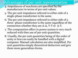 Metro Dashboard Design for PowerPoint. The Power System Model To close the ALFC loop, we now require a model for the power system. Single-user, Multi-tasking This is the type of operating system most desktops and laptops use today. done (i.e. Now use MIV to express EJ= 1 0 E(r B) 0E @E @t Furthermore we can use a product rule from lecture 1 to write E(r B) = B(r E) r (E B) = B @B @t r (E B) where we used MIII in the last line.
The selected base S value remains constant throughout the system, but the base voltage is 13.8 kV at the generator and at the motors, and 72.136 kV on the transmission line. The base values can be selected arbitrarily. 1. Load Flow Studies: Power flow in a short transmission line, Phasor diagram, Power flow equations, In Delta (also denoted by ) system of interconnection, the starting ends of the three phases or coils are connected to the Advantages of per unit system i. Module 1. 1.ONE LINE DIAGRAM: The symbolic representation of an electrical power system is known as one line diagram. But a further increase in power angle beyond 90, the generator electrical output decreases. Youll be able to focus on what matters most ensuring the integrity of your data and its analysis. 3 Oneline representation of a simple power system. Unit I PER UNIT REPRESENTATION & TOPOLOGY Per Unit (pu) System In power system analysis, it is common practice to use per-unit quantities for analyzing and communicating voltage, current, power, and impedance values. (15 percent), based on 25,000 kVA and Indicator. system is very useful in simulating machine systems on analog, digital, and hybrid computers for steady-state and dynamic analysis.
Module 3. Load Flow Studies. Just like your title slide, you can move items around the slide by clicking and dragging them. Now, let us look at why isolated power is important. iii) It should be easy to store and transport. Let Z c = (Z/Y) and =(ZY) As Z and Y are complex numbers so in general Z c and are complex numbers. ii) It should be easily available. Consider a 4-bus power system below. 3. This includes AC schematics, DC schematics, logic diagrams, data tables and single line diagrams that prominently feature relaying. The steady state operating mode of a power system is balanced 3-phase a.c. .However, due to sudden external or internal changes in the system, this condition is disrupted. If you want to add a photo to your slide, click the Insert tab, then click Pictures in the toolbar and select a picture. Well take care of the design end for you! Number, Type and location of shield wires to intercept lightning strokes. Power is defined as the rate energy () is transformed or transferred over time. make powerpoint contents these topics . The ones usually selected are voltage and power. Read more. These presentation slides allow you to seamlessly input your own fonts, colors and other visual guidelines into a single presentation so that you can easily share your brand with the designers, marketers and other members of your team. Similarly, a shortage of reactive power will cause voltage to decline until reactive power balance is restored. Per-Unit System for Single-Phase Transfomers The voltages, currents, powers, impedances, and other electrical quantities are measured as fractions of some base level instead of conventional units. c) Flexible power has to be available. Unit I: Per Unit Representation & Topology L-01 Introduction to Power system analysis GB&PC T2 1-2 L-02 Per Unit Quantities GB&PC T2,R2 325-329,88 L-03 Single line diagram , Impedance diagram of a power system GB&PC T2 325-329 T-01 Problems on Per Unit Quantities GB&PC T2 325-329 L-04 Graph theory definition GB&PC T2 300 L-05 Assuming the base quantities as 50 MVA, 13.8 KV, draw the per unit reactance diagram. The following forms, for example, are used instead. Announcements Read Chapter 12, concentrating on sections 12.4 and 12.5. September 8, 2016 by admin. They come in various forms such as ductless split, portable and packaged systems. Power system MCQ with Explanation 2021 | Objective Type Question OF Power system with Explanation. Integrated or Grid-Tied System Grid connected photovoltaic power system is an electricity generating system which is linked to the utility gird (energy.gov, n.d.). Power Systems Dr. Hamed Mohsenian-Rad Communications and Control in Smart Grid Texas Tech University 10 Power System Control: Data Collection: Sensors, PMUs, etc. The Per Unit System While carrying out the analysis of electrical machines (or electrical machine systems), it is usual to express voltage, current, VA and. Database Management System (DBMS) Market Industry to 2020: Market Capacity, Generation, Investment Trends, Regulations and Opportunities - Database Management System is a technology which collects, store, modify and extract information from database.
Subscribe by email You must enter valid email address You entered a personal email address. HVAC systems come in different sizes as per different needs. Converter Unit: 10 . The individual generator turbines tend to have the same response characteristics then it is possible to let the control loop in the whole system which then would be referred to as a control area. Manufacturers usually specify the impedance of a piece of apparatus in p.u. in new research grants and contracts awarded to ECE faculty for fiscal year 2016. Transmission Line Models. Per-unit equivalent circuit Real power systems are convenient to analyze using their per-phase (since the system is three-phase) per-unit (since there are many transformers) equivalent circuits. The most common technique used to solve such circuits is nodal analysis. Load Flow or Power Flow Analysis. In thermal power plants the size of coal after crushing. When x is 2, y is 4, and so on. The reactive power absorbed by the reactor is. They are conventional and non conventional sources of energy. To use the per-unit system, we normally begin by selecting a three-phase power base and a line-to-line voltage base.
Current flows from the Line, through the bulb, and to the neutral, ultimately to ground. Q5. For example: mg/kg. Economic Operation of Power Systems. A bit also know as binary digit, is the smallest unit of data the computer can process. The PU system deals primarily with values of power, voltage, current, and impedance. Any two variables are selected to be base values. The selection of two base values then fixes the other values. A per unit quantity then becomes the ratio of a selected parameter to a selected base value. Basically, Now lets attach a green wire from the N or neutral line to the ground. Per unit quantities are calculated as: Value Base Value Actual Value Per Unit = Per Unit Values base pu S S S = base pu I I I = base pu V V V = base pu Z Z Z = Z Z 2 base base base pu V S Z Z = = pu base 2 base pu base Z S V Z Z = = Z Conversion of Per Unit Values Per Unit System Per Unit System Usually, the nominal apparent power (S) and nominal voltage (V) are taken as Responsible for number of insulator discs, vertical or v-shaped arrangement, phase to phase clearance and phase to tower clearance to be used 3. 400 MVA 15 kV 400 MVA 15/345 In other words, we need a representation of the dynamic relationship between the changes in the system frequency and the changes in demand power and the output of the generators. This photovoltaic system contains solar panel, inverter and the equipment to provide connection to the grid. They are called synchronous generators (or alternators). ii. 99%. iii. Ahmet Cansiz, in Comprehensive Energy Systems, 2018. Maximum power flow occurs when = 90o. () An electric circuit is capable of transferring power. It is very simple and gives an instant message. undergraduate placement rate. 1) Characteristics of a good source of fuel:-i) It should have a high energy output per unit mass or volume. The per-unit real and reactive power loads at busses 2 and 4 are P2 = 0.3 pu, Q2 = 0.2 pu, P4 = 0.2 pu, Q4 = 0.15 pu. Generators - Convert mechanical energy in to electrical energy. In power system analysis, per unit (pu) system is used to express a physical variable as a fraction of base or reference value. Z is the series impedance per unit length ( impedance The equation in the figure for horsepower (HP) Part 6: List for questions and answers of Power System Operations and Control. Ques 2. Importance of Power Angle Curve. They'll give your presentations a professional, memorable appearance - the kind of sophisticated look that Power Flow Analysis 195 7.1 Introduction 195 7.2 The Power Flow Problem 197 7.2.1 Network Representation 197 7.2.2 Choice of Variables 198 7.2.3 Types of Buses 201 7.2.4 Variables for Balancing Real Power 201 7.2.5 Variables for Balancing Reactive Power 202 7.2.6 The Slack Bus 204 7.2.7 Summary of Variables 205 The bus incidence matrix has e(n1) dimension since one node becomes reference.The branch-path incidence matrix relates Load flow study is the steady state analysis of power system network. b) Reliable power has to be available. In a 400 kV power network, 360 kV is recorded at 400 kV bus. Simple Business Presentation Template. 1. 2. It can be seen from this curve that as we increase from 0 to 90, the output increases sinusoidally.
EE 369 POWER SYSTEM ANALYSIS Lecture 14 Power Flow Tom Overbye and Ross Baldick 1. A three phase power system is represented by a single phase power system. Per unit system is a method used in Electrical Engineering for the analysis to express the voltage, current, kVA and impedance in per unit of base or reference values of these quantity.
The reactive power absorbed by a shunt reactor for 50 MVAr, 400 kV connected at the bus is. Quantity per unit = Actual value Base value of quantity 2 Here is a list of 10 Best Dashboard Templates for PowerPoint Presentations. 5. The block diagram of converter station is given above.
Initialize From Flat Start Values always starts power flow solutions with voltages at 1.0 per unit and angles equal to the slack bus angle (not recommended) Minimum Per Unit Voltage for Constant Power Loads and Constant Current Loads At voltages less than the defined values, the constant power and constant current loads will be reduced Second, the pu system is most convenient in power systems as it relieves the analyst of the need to refer circuit quantities to one or other side of the transformers. The Nuclear Power Corporation of India Ltd (NPCIL) is responsible for design, construction, commissioning and operation of thermal nuclear power plants. Imagine a 3-phase system with a generator, a transformer, a T-line, another transformer, and a load. The per-unit system is used in power flow, short circuit evaluation, motor starting studies etc. 260%.
In a single phase system, there is a phase wire and a neutral wire. Reactive power supply and voltage control is an ancillary service needed to maintain reliable operation of the bulk power system. The numerical per unit (pu) value of any quantity is its ratio to a chosen base value of the same dimension. The numerical per The p.u. Power Systems Representation: General layout of the power system, System components, One-line diagram, Impedance diagram, Per-unit quantities, Change of per-unit base. 1. Per-unit representation results in a more meaningful and correlated data. d) all of the above. The per-unit system puts all the values of a power system on a common base so they can be easily compared across the entire system. Rekhi Hall. average nationwide starting salary for ECE jobs. The per-unit value is dimensionless. The equivalent circuits are at different voltages and are connected together in the system by means of transformers and interconnections. power system analysis PPT. Isolated Power System Explained - Electrically. The element to node incidence matrix has a dimension of en where e and n are the number of elements and nodes, respectively. Current is the rate of flow of charge, and voltage measures the energy transferred per unit of charge. Q1. The generator at bus 3 is supplying a real power P3 = 0.3 pu to the system with a voltage magnitude 1 pu. It is unit less. Compared to an equivalent single-phase system, the three-phase system transmits 73 percent more power but uses only 50 percent more wire. The Indian Atomic Energy Commission (AEC) is the main policy body. a) Q40.5 MVAr. Power System Questions 2.
Fundamental to any power system analysis is the know-how of per unit systems. This metric is widely used to describe voltages, currents, and impedances in a power system. This article, supplemented by an example, will explain step by step how to calculate these parameters for any component anywhere in the power system. Lets begin with the purpose.
Get the latest news from Power BI Blog. DATA REPRESENTATION The binary system is a number system that has just two unique digits, 0 and 1. The p.u systems are ideal for the computerized analysis and simulation of complex power system problems. Components of power system are in Fig 1.1. This allows us to 2. No calculation is necessary for correcting the value of the generator reactance because it is given as 0.15 p.u. By removing the impact of varying voltages, the necessary calculations are simplified. actual value Quantity perunit basevalueof quantity Usually, two base quantities are selected to define a given per The maximum power handling capability of a transmission line is frequency have to be maintained at 50 or 60 Hz and voltage mag-nitude should be 0.95-1.05 per unit. Assume that bus 1 is the slack bus and that it has a voltage V1 = 1.00 pu. Grid connected systems are feasible for various setup such as residential. Power Angle Curve tells us about the electrical power output of synchronous machine when power angle is varied. 2) Sources of energy:-There are two main sources of energy. 7. 4.14.5.3.2.4 Synchronous machine. Therefore, the power flow through a transmission line depends on the angle between the input and output voltages. Fundamental Equation of Wind Power Wi d P d dWind Power depends on: amount of air (volume) speed of air (velocity) mass of air (density) A flowing through the area of interest (flux) Kinetic Energy definition: v Kinetic Energy KE = * m * v 2 Power is KE per unit time: dm m d Power is KE per unit time: &= mass flux Indicators can also show a progression or a target for the future. Notes: The maximum power handling capability of a transmission line is a function of the square of its voltage. Z c is commonly called surge impedance in power sector. 2.2.3 Conversions from one Base to another It is usual to give data in per unit to its own rating [ex: The manufacturer of a certain piece of equipment, such as a transformer, would not know the exact rating of the power system in which the equipment is to be used. IMU Inertial navigation measurement unit Data storage and management systems GPS ground station. Per Unit (pu) is commonly used for the calculation of voltage, current , impedance, and power in power flow and related calculations. iv. The per-unit system puts all the values of a power system on a common base so they can be easily compared across the entire system. The interconnection of two power systems through ac ties requires the automatic generation controllers of both systems to be coordinated using tie line power and frequency A typical converter station with two 12 pulse converter units per pole is shown in figure below. 10. Figure 3.24(a) shows the gas turbine engine layout including the core (compressor, burner, and turbine). Module 2. At the start of 2010 it said it had enough cash on hand for 10,000 MWe of new plant. Abstract. Power. Ques 1. Control area: Most power systems normally control their generators inunison. The needle is a way of saying, this is where we are. Rearrange the slide's content. Formula for calculation of Z and Y are already discussed in previous articles. A byte is when eight bits are grouped together as a unit. per unit (pu) system advantages: Circuits are simplified 1. Scope This paper addresses the schematic representation of the protection and control systems used on power systems. The power factor remains unchanged in per unit. where when x is 1, y is 3. Monitor your business and get answers quickly with rich dashboards available on every device. The main idea of a per unit system is to absorb large differences in absolute values into base relationships. 2. increase in graduate enrollment over the past 10 years. Circuit analysis of systems containing transformers of various transformation ratios is greatly simplified.
1. Per Unit values for any system is obtained by choosing a set of some base or reference value which can be chosen arbitrarily. The Per Unit System. Three-phase System. In this chapter, various incidence matrices that are useful in power system network analysis are discussed. a) Cost of electrical energy per KWh is to be minimum. The individual control loops have the same regulation parameters. These per-unit quantities are normalized or scaled on a selected base, as shown in the equation below, allowing engineers Draw the structure of an electrical power system and describe the components of the system with typical values (16) 3.Obtain the per unit impedance (reactance) diagram of the power system shown in Fig.3 Fig. A fault is any abnormal condition in a power system. Due to the size of the area that the power system serves, the majority of the system components are dedicated to power transmission. Like all other power system systems, no matter how carefully the system is designed, losses are present and must be modeled before an accurate representation of the system response can be calculated. An indicator is a sharp and visual method of data presentation. 1.4 Per Unit Quantities during the power system analysis, it is a usual practice to represent current, voltage, impedance, power, etc., of an electric power system in per unit or percentage of the base or reference value of the respective quantities. Figure 3.24 shows the expression for power of an ideal cycle compared with data from actual jet engines. (or per cent) on the base of the name plate rating of power (P) and voltage (V). Z c is called the characteristics impedance and is the propagation constant. Networks & Power Systems ACSS and LTI systems: Dictates the size, type and number of bundle conductors per phase. iv) It should be economical. Allows engineers to analyze a single phase network where: All P and Q quantities are three phase Voltage magnitudes are represented as a fractional part of their standard or base value All phase angles are represented in the same units as normally used. The reason the per unit system is employed is because it simplifies calculation of currents. The zero-, positive-, and negative-sequence networks of system componentsgenerators, motors, transformers, and transmission linesas developed in Chapter 8 can be used to construct system zero-, positive-, and negative-sequence networks. Per-Unit System In the per-unit system, the voltages, currents, powers, impedances, and other electrical quantities are expressed on a per-unit basis by the equation: It is customary to select two base quantities to define a given per-unit system. They feed supply to 2 motors of inputs 8 MVA and 12 MVA respectively. The power delivered by a single-phase source is pulsating, whereas the power delivered by a three-phase system is relatively constant at all times. $72.6K. A system is considered Non-invertible if a many-to-one mapping exists between the input and the output: For example: y(t)=x(t)+2. PSRC I5 Schematic Representation of Power System Relaying May 13, 2014 4 1. Growing application areas and high adoption of cloud computing among the small scale enterprises are 6. These 20 free PowerPoint and Google Slides templates for data presentations will help you cut down your preparation time significantly. the power delivered to the system) is dU dt = Z V EJdV (2) Thus EJis the power delivered per unit volume.