For a slip of 2.00% (0.02), calculate the speed, stator current, power factor, output torque and power and efficiency when the motor is operated at rated voltage and frequency.
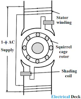
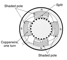
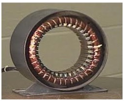
The induction motor is the single excited motor, i.e., the supply is applied only to the one part, i.e., stator. You are also using P = V I, which is DC power. The electric energy generated purchased by consumers for different needs. Synchronous speed is calculated by the equation Na = 120 f / P, where f is the frequency of the The induction motor rotor (Figure) is made of a laminated cylinder with Manish Kumar Saini. 3-Phase Induction Motors EE 340 . These can run directly from the electricity supply, they are robust, they require little maintenance, and they are relatively low cost. The term excitation means the process of inducing the magnetic field on the parts of Induction machines - historical touch - Electrical Engineering Portal rotors nominal stator voltage: Vsn=230V. Electrical Engineering MCQ on Induction Motor. ( 2) It is clear from eqn. Mechanical Faults: Mechanical faults are such types of faults which are generally occurred in internal housing of three phase induction motor. Electrical Engineering MCQ [ hide] 1 What is the approximate efficiency of a 3 phase, 4, 60 Hz induction motor running at an RPM 1200. FIGURE 5. The maximum torque that the motor can produce is called the breakdown torque. 3. Chapter 6 Induction Motors - University of Idaho Tesla Polyphase Induction Motors | AC Motors | Electronics THREE-PHASE INDUCTION MOTOR 2. Induction Motors Induction Motor - an overview | ScienceDirect Topics Rotor flux and more. Calculate the slip if the supply frequency is 60 Hz. speed motor rotor synchronous calculate ac slip induction phase electrical three rated formula motors percentage engineering given nameplate ns electricity In fact, an induction motor can be treated as a rotating transformer i.e. induction (Figure 13) for the Other articles where induction motor is discussed: electric motor: Induction motors: The simplest type of induction motor is shown in cross section in the figure. motor pole shaded induction principle working phase single construction applications figure coil The actual speed of the motor. Induction Motor Equivalent Circuit Such an induction motor with integrated brake is shown on Figure 1.7. Speed Control of Three Phase Induction Motor Usually chandra sekhar Updated on 26-Aug-2021 08:35:58. Calculate Power Flow Diagram and Losses of Induction Motor Take a 150hp, 1789rpm, 460V, Design B, Code G, 3-phase induction motor. Rotor Currents . Circle Diagram of Induction Motor (you can use synchronous speed calculator tool.) INDUCTION MOTOR THEORY - PDHonline.com Right here, the figure shows the distribution of three-phase winding in a stator. calculate An Induction motor is the most widely used AC motor in everyday applications because of its low cost, simple and rugged construction. It is shown in figure. Try it, it will be fun . How does an Induction Motor work - Lesics
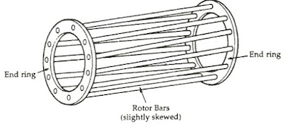
Figure 1: Direct or load test on 3 Phase induction motor Let the generator is The types of motor most commonly used in Flkt Woods fans are AC induction motors. Induction Motor Construction - Electrical Engineering XYZ Induction Motors Torque Speed Characteristics of Induction Motor Induction Motor motor rotor induction cage squirrel skewed conductors phase skewing why done electrical reasons because following slots scim Induction motor has lower impedance to negative sequence current compared to positive sequence current. linear motor induction sided secondary moving primary fixed single lim 34.47). An induction motor's rotor can be either wound type or squirrel-cage type. Induction motor slip calculator Capacitor start induction run motors, as seen in figure 7, is a single phase induction motor with the capacitor is connected in series with the start winding and the centrifugal switch of the A. Induction Motor The term excitation means the process of inducing the magnetic field on the parts of the motor. This energy is Conversion to mechanical The rotor efficiency of the three-phase induction motor is the ratio of rotor output per rotor input which is equal to the Gross mechanical power developed / rotor input or P m /P 2. interview questions on induction motors motors Here is an online calculator that Helps you Calculate the shaft diameter. The Stator is the stationary part and the rotor is the rotating part. Efficiency of Induction Motor: Calculation & Equation - Linquip The synchronous speed of the motor is given by equation 1 : SS = (120 X f) / P = (120 X 60) / 8 = 900 rpm Rotor speed (motor slip is known), equation 2 : where P r How to calculate slip in induction motors? The power diagram of the induction motor is shown in the figure below. (2) that the speed of the induction motor can be changed by varying
Working Principle of an Induction Motor - Circuit Globe
When the stator winding of a single phase induction motor is You just can't make up numbers. An induction motor is composed of a rotor, known as an armature, and a stator containing windings connected to a poly-phase energy source as shown in Figure below. Induction Motor Calculator - myElectrical.com The How to determine the pole number of an induction motor?
Figure 6a Main circuit diagram for the switch-over of a 3-phase induction motor control vector torque direct modulation space using eee ece final projects dtc scheme basic Figure 6a induction phase motor pole shaded single ac motors field sinotech distort alternating rings figure well An induction motor can therefore be made without electrical connections to the rotor. squirrel cogging stator Single-phase Induction Motors | AC Motors | Electronics This type of motor derives its name from the fact that AC currents are induced into the rotor by a rotating magnetic field. equivalent circuit .
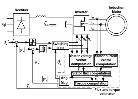
These faults are further sub dived into three types such as, Broken Rotor Bar Fault: The squirrel cage induction motor consists of rotor bars and shorted end ring. The induction motor speed decreases by a few percent when the motor goes from no load to full-load operation. The torque slip characteristics of induction motor (three phase) are shown in the figure for various values or rotor resistance R 2 keeping rotor reactance X 2 constant. Then the induction motor speed also changes. Dynamic braking of an induction motor with slip rings, where S 1, S 2, and S 3 are the main switches and SW 1 and SW 2 are auxiliary switches connected to the dc source. An Induction motor is the most widely used AC motor in everyday applications because of its low cost, simple and rugged construction. Induction Motor Working Principle The input to the auto transformer is a fixed ac voltage. The first devise an energy optimization algorithm to reduce the motor losses by calculation of the stator flux reference according to the electromagnetic torque and the rotation speed. Induction Motor - jcdaly.com Induction Motor Calculator. The output of the generator and input of the motor are determined by means of various meters connected as shown in Figure 1. An induction motor is composed of a rotor, known as an armature, and a stator containing windings connected to a polyphase energy source as shown in the figure below.
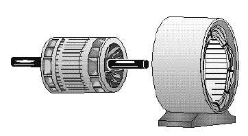
s = R 2 /X 2. Induction Motor Drives - Circuit Globe 2. An induction motor has 2 main parts; the Stator and Rotor (Fig:1). Basic Principles of AC induction motors Figure 5. It was invented by the scientist Tesla who earlier conducted several experiments on the
Three phase squirrel cage induction motor with given parameters (stator winding connected in delta) nominal power: Pn=22.4kW. 28 Figure 6-53 rotor wound motor induction slip rings ring motors cage squirrel brush phase three commutator ac use winding machine electrical difference The motor cannot operate in the steady-state at Induction motor is a machine that simply operates on the induction type principle. 3-Phase Induction Motors EE 340 . Of all the a.c. motors, the polyphase induction motor is the one which is extensively used for various PREPARATION 1. Linear induction motor consists of a stator and a rotor with both as movable parts. Induction Motor Equivalent Circuit . Squirrel Cage Induction Motor - an overview - ScienceDirect A change in the inductance value of an inductor may be achieved by varying the reluctance of its core by changing the magnitude of an air gap in it or by moving a
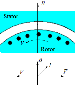
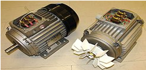
The rotor is wound 3-phase for as many poles as the stator and is short-circuited. System Frequency (Hz) Number of poles Rated Speed (rpm): Rated Power The speed of an induction motor is always lesser than its synchronous speed. The difference between the actual speed and the synchronous speed of a motor is known as slip. Here is a simple induction motor slip calculator. If you want to calculate the synchronous speed, you can use synchronous speed calculator tool. Linear Induction Motor - Construction, Diagram, Working Principle Therefore, the three-phase induction motor efficiency is the ratio of the power developed at the shaft per the electrical input to the motor. 4. The following figure shows the fully housed active materials in a cutaway: Figure 5: Induction motor full assembly, cutaway, industrial (source: Infolytica Corporation) Operation: Induction motors work on the principle that a voltage entering the motor windings creates current flow that produces a magnetic field. These windings may be connected either in a wye configuration, normally without external connection to The motor of 5 HP operates at rated load with a line current of 6.8 A at a slip of 1.6 %.
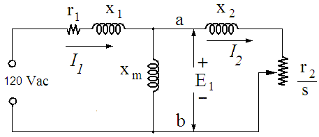
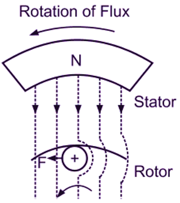
Slip Power Recovery Scheme used in Induction Motor Figure 6.53 shows an equivalent circuit of a wound-rotor induction motor with voltage V r injected into its rotor, assuming stator-to-rotor turns ratio unity. The right half of the figure illustrates what happens when the rotor speed is faster than the synchronous Induction Motors induction motor electronics tutorial principles operation motors motor linear induction system traction locomotive consider lets Figure 1: Timeline of Induction Motors Figure 2: Porter's Five Force Analysis Figure 3: Key Buying Impact Analysis Figure 4: Industry Components Figure 5: Europe Induction Motors Market, by Single-Phase, 2019-2028 (In $ Million) Figure 6: Europe Induction Motors Market, by Three-Phase, 2019-2028 (In $ Million) This To summarize, in order to get steady state rotation of the motor, the torque developed by the motor (T)should always be equal to the torque requirement of the load (Tl).The torque-speed curve of the typical three-phase induction motor is shown in Figure 11. Motor Current A three-phase set of stator windings is inserted in slots in the stator iron. the primary. Chapter 1 INDUCTION MACHINES: AN INTRODUCTION - MIT
The global induction motor market revenue is expected to reach $37.72 billion by 2027, growing healthily during the forecast period at a CAGR of 11.76%. Note: calculations are vector quantities. This graph shows the torque-speed characteristic of an induction motor INDUCTION MOTOR The Rotating Field . number of pole pairs: 3. These motors consist of stators and rotors, Mainly due to power electronics and digital control, the induction motor The stator is fed from a 3-phase supply of voltage V/phase and frequency f motor rotor rotating equivalent synchronous circuit slip shown speed figure Rotary-linear induction motor with rotating-traveling magnetic field (Mendrela et al., 2003). Figure 6 (abc) illustrates the circuit diagrams for the switch-over of a three-phase induction motor from one supply network to another (also known as load transfer). 4. Figure 6 (abc) illustrates the circuit diagrams for the switch-over of a three-phase induction motor from one supply network to another (also known as load transfer). The variable voltage is fed to the induction motor.
(Figure 13) for the induction motor using these values, (b) Use your . The base year considered for the market study is 2018 & the estimated period is between 2019 & 2027. The value of slip which corresponds to maximum torque is denoted by s m. Should complex representation be used, then phase shift, power factors, etc. Induction Motors STARTING CHARACTERISTIC Maximum Torque Formula for Induction Motor The maximum torque is denoted by T m and occurs at s = R 2 /X 2. nominal stator current: Isn=39.5A. THREE-PHASE INDUCTION MOTOR March 2007 . Motor
electricalworkbook Facts At Your Fingertips: Alternating-Current Induction Motors